|
|
 |
Lostock Junction
and the
Serious construction on the site began in 1977 with the excavation of a pit in the crawl space.
The layout is simple large, 45 feet x 24 feet with over 700 feet of track in 00 gauge.
To keep such a large privately owned layout operational, reliability must take priority over detail.
|
|
|
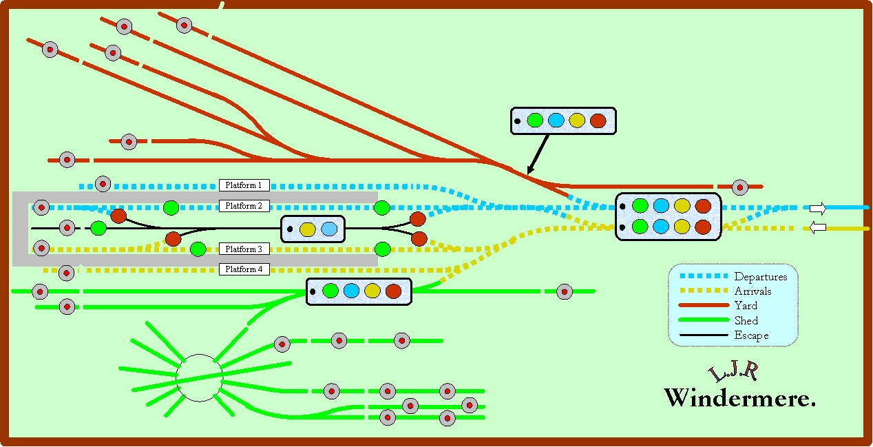
Approach to the
layout is through the basement where there is a 22’ long replica of Windermere
station.
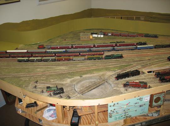
This is not quite a true Windermere as the real Windermere did not have the extensive locomotive storage facilities we require to house our motive power.
A major step was accomplished in January 2007 when Windermere opened to traffic.
Also in this area is the cassette storage facility which can accommodate over 16 trains up to 8 feet in length.
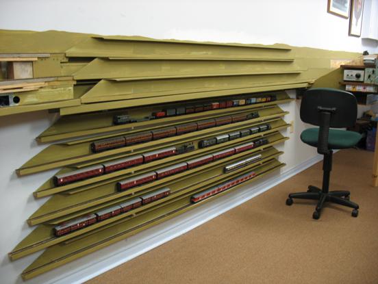
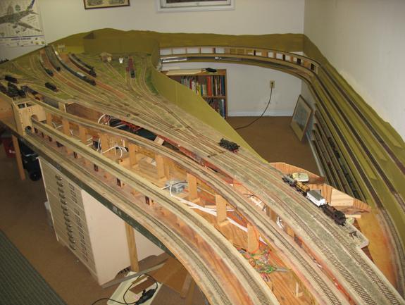
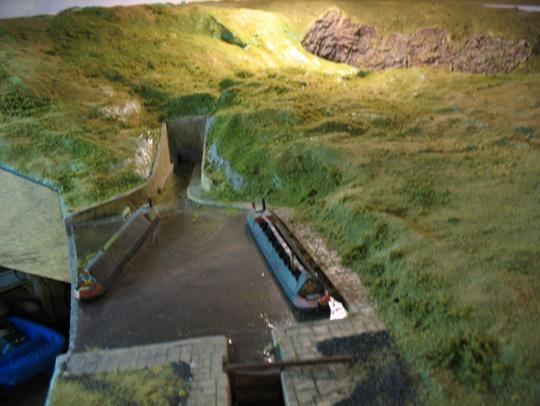
Passing Windermere, one steps down
into the pit area. This room (24’ x 21’) reflects structures of the Settle and
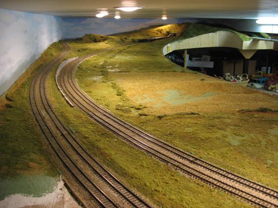
An earlier versions of the layout used wooden support structure which sagged over time.
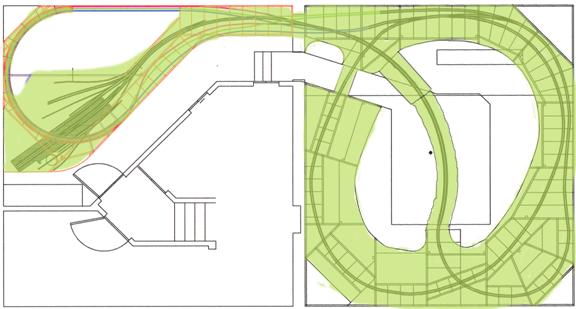
The present layout is constructed on lightweight steel studs laid out as show below.
There have been no sagging problems since. The layout of the steel studs can be seen in the diagram below.
Seven or eight operators are needed to reach the fully operational potential.
To enable new operators to come up to speed quickly, the control system was designed to be as intuitive as possible.
Simple touch panels are used to assign blocks and set points.
There a two overall layout control panels as shown below. One is located at Lostock and the other at Windermere.
The control panel for the shed operator at Windermere is shown below.
There is a functionally identical panel for the goods yard operator but it is a mirror image of the one below to match the orientation of the operator.
|
|
|
Where possible the wiring has been simplified by using modular components.
Most of the electrical switching from the 11 controllers takes place on two central interchange panels to which 5 remote touch panels are connected by cable.
From the start it was recognised that most visiting engines would not be fitted with DCC so standard 12 VDC had to be accommodated.
While DCC control option was provided in the original planning, it was eventually dropped as unsuitable for our type of operation.
Trains on Lostock are passed through a string of operators controlling a section of track they see.
With this method of operation, DCC applied conventionally is impractical.
There are two central panels on which all the modules are mounted and through which most cables are routed.
The Lostock panel is shown below, the Windermere panel is similar.
The layout really came to life in
2002 when operating sessions with the
Since then we have had over 50 operating
sessions punctuated by my breaks from work in
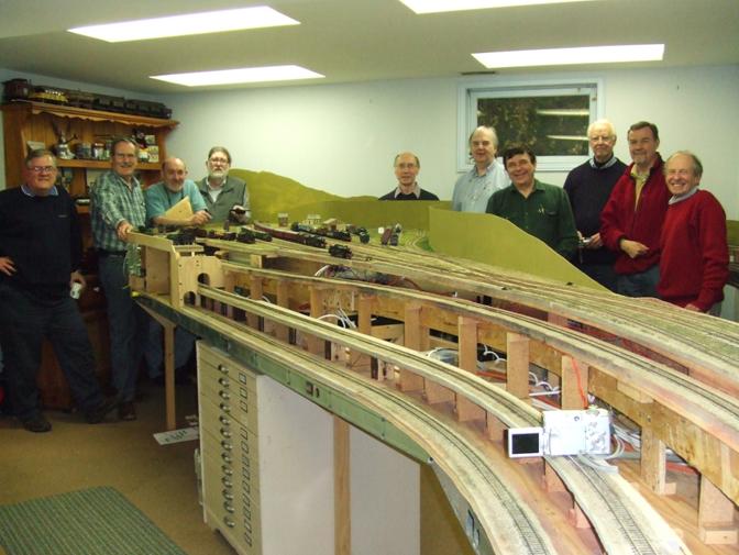
The above photograph of the
Left to right, Greg
Georgeff (visitor),
While working in
If the
The opening of Windermere at the beginning of the year presented new and unforeseen challenges. Injecting and extracting trains at Windermere into a stream of trains passing at one minute proved to be impractical with the existing distribution of work amongst the operators. To solve the problem, a new operating position at Preston Junction was created and the control system extended to support this move. This will also free up operating space near the cassette storage facilities thus allowing an even a greater variety of rolling stock to be operated.
Altogether there are over 5000 soldered connections to the colour coded “Bell Type” cables. The wiring configuration is conveniently maintained on Excel workbooks which are also used to print the terminal strip labels.